Overview
Swissloop is an ETH Zürich Hyperloop student team where ~38 students build a new prototype from scratch each year. In 2022/23 I was one of five full‑time electrical engineers on «Bertrand Piccard», Swissloop's first fully levitating pod.
At European Hyperloop Week 2023 in Edinburgh the team won 5 of 10 awards, including the main Complete System Award, plus Electrical Subsystem, Traction Subsystem, Sense & Control, and Thermal Management.
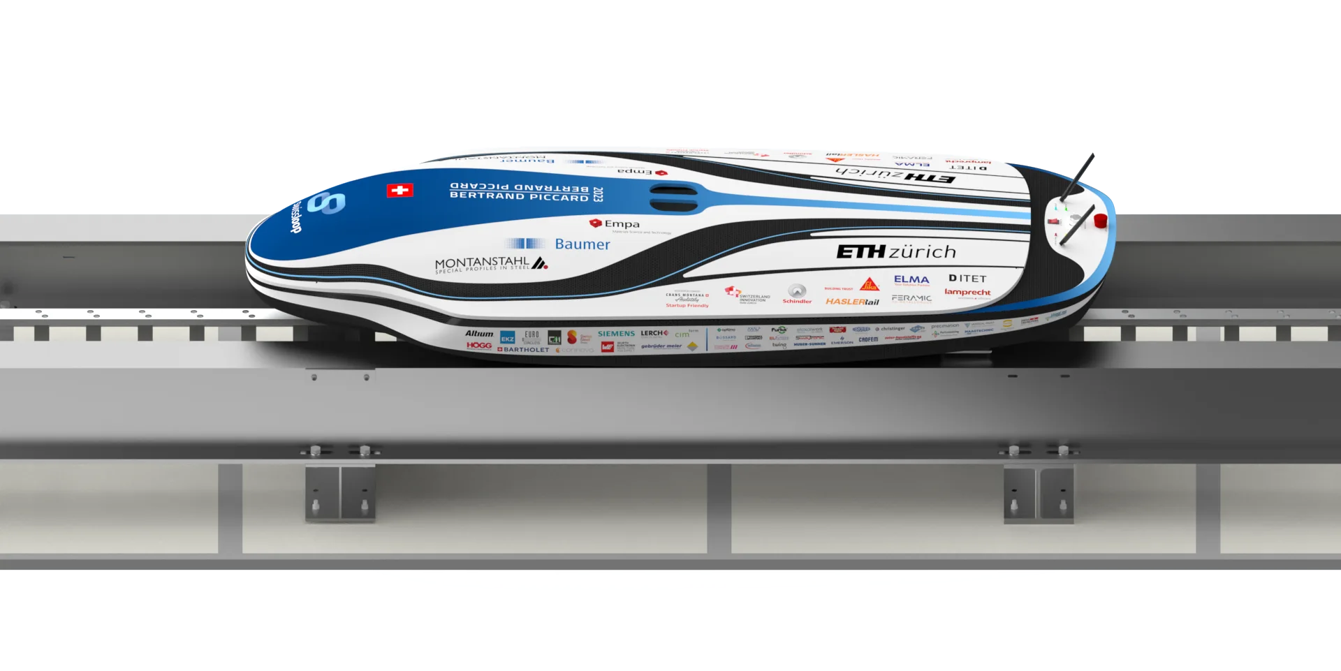
Pod «Bertrand Piccard»
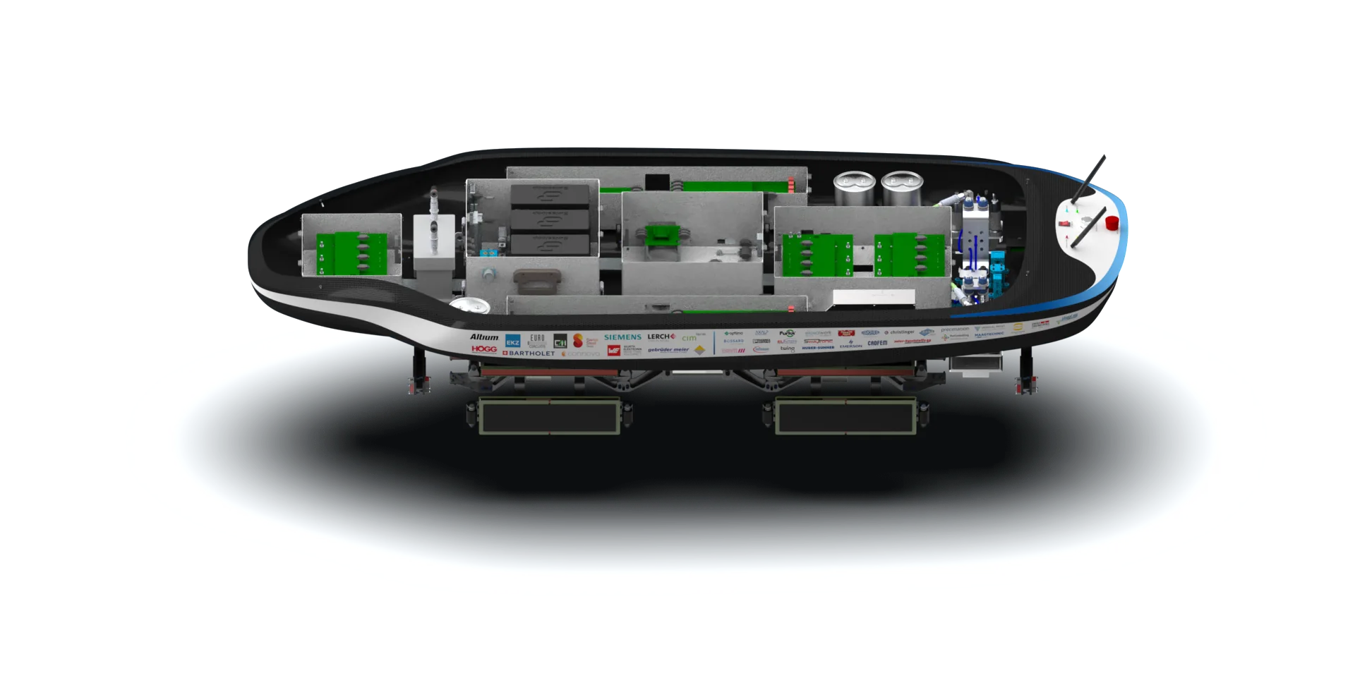
A 21 kg carbon‑fibre monocoque housing a linear switched reluctance motor, electromagnetic levitation & guidance, phase‑change cooling and a 24‑module LiPo battery.
Exploded view of the pod subsystems
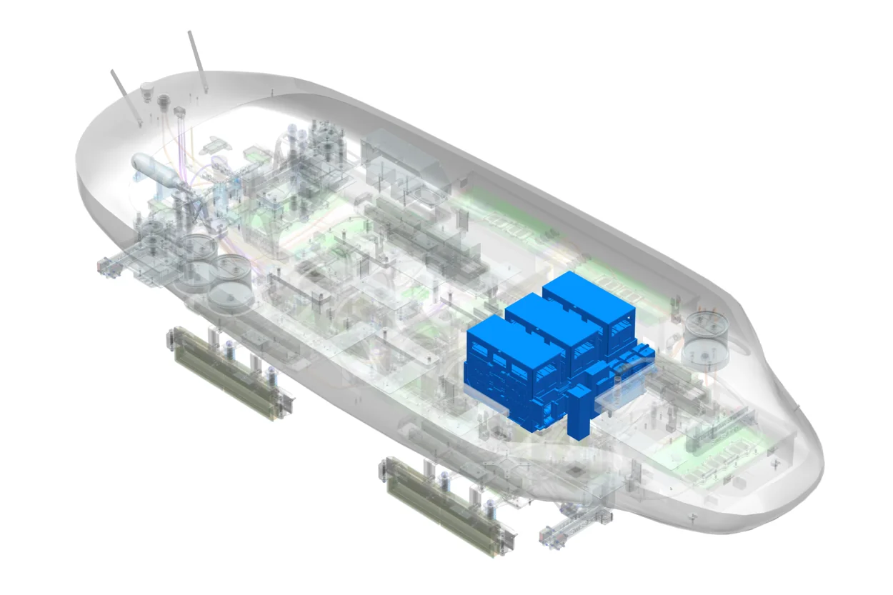
Inside the battery box
My bachelor's thesis was the pod's high-voltage power supply: 24 LiPo packs (192 cells) in a single 26 kg box, and the battery management system that decides when, and how, up to 823 V reaches the propulsion and levitation inverters.
An FPGA sits between the microcontroller and the relays. It only passes these four relay combinations, inserts 60 ms of dead time between changes and opens everything on its own on an overcurrent or isolation fault. The capacitor voltage follows R·C = 100 Ω × 2.1 mF = 0.21 s.
Voltage and temperature of all 192 cells through 12 daisy-chained slave boards, plus pack current and voltage sampled at 5 kHz.
An STM32H7 running FreeRTOS executes the state machine above and reports to the vehicle control unit over isolated CAN FD.
Relay logic in hardware, an isolation monitoring device, its own low-voltage supply, and every critical check implemented in both hardware and software.
My Contributions
- Designed and operated the 800 V / 250 A battery system: 24 LiPo modules in one box with integrated BMS and isolation monitoring.
- Developed BMS hardware (Altium) and firmware in C/C++ and SystemVerilog for STM32H7 and FPGAs.
- Implemented real‑time monitoring of 290+ safety sensors over CAN‑FD for autonomous fault detection.
- Helped upgrade the power electronics from 400 V to 800 V, including propulsion and levitation inverters.
Thesis & Publication
The battery and power supply design became my Bachelor's thesis at ETH Zürich.
View PublicationPod Run
Run 1: 58.8 km/h after 30 m of acceleration. Runs 2 and 3: fully contactless static and dynamic levitation.